JoeFischer Designs
ANALYSIS
DESIGN
Several designs were explored for this project. Many of the parameters for this project include:
-
Number of spokes
-
Spoke geometry
-
Material
-
Tire type
-
Method of collapsing
-
Hub / Axle configuration
-
Hinging, fixtures, clasping, bolting, etc.
-
Material thickness
These parameters were chosen based on the desired requirements as seen on the Intro page. Figure 1 shows the three major design iterations during the design process.
The final version is a 6-piece 6-spoke design. This design was chosen because it:
-
Reduces frontal area without sacrificing too much depth or assembly time.
-
Promotes weight capacity compared to 4-spoke model.
-
Allows for thinner spokes than 4-spoke model.
-
Allows for lighter overall weight than 8-spoke model.
-
Reduces assembly time with new hub design and push rim mounts.
Even though the 6-piece design have more depth and a longer assembly time, its vast reduction in frontal area was deemed worthwhile. See Table 1 for a comparison of properties based on different designs.
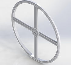


Figure 1: Several iterations of the Collapsible Wheelchair Wheel design. Initial 4-piece 4-spoke wheel (top), 4-piece 8-spoke wheel (middle), & final 6-piece 6-spoke wheel (bottom).


MATERIALS
Many materials were considered. The overall material was narrowed down to plastic and aluminum based on other competitive wheelchair wheels. Some important factors considered when chooisng a meterial for this project were:
-
Tensile & Shear Strength
-
Weight / Density
-
Cost
-
Availability
-
Machinability / Weldability
Though a plastic polymer would've been lighter weight, ultimately, ALUMINUM 6061-T6 was chosen as it met all the requirements, allowed for the maximum weight capacity, and cost a fraction of the cost of the plastic required to meet the same strength.

METHOD OF ANALYSIS
To meet the requirements and achieve the most compact collapsible, with minimum frontal area, many components and methods had to be analyzed before constructing. Some major areas of analysis include
-
Spoke geometry
-
Spoke locking
-
Hub design and connections
-
Deflection at critical locations
-
Material choice
All these parameters are directly influenced by the 250-pound weight capacity requirement.
First, an Excel spreadsheet was set up to analyze different designs with different number of sections. These spreadsheets were based on free-body diagrams of each design and relative force, moment, buckling, endurance, and stress calculations. The spreadsheet for the final 6-piece design shows the force, moment, and stress in each spoke when subject to the maximum load. The spreadsheet also conpares both Aluminum and Nylon plastic and determines if the material will fail in any spoke.
Second, calculations were done on the hub pieces to determine if they would shear under maximum load. Inversely, calculations were done to determine the number of bolts to use and the size of the bolts for the hub so they wouldn't fail under max. load as well.
Third, SolidWorks was used to do finite element analysis on unique, non-uniform parts and also to validate and compare stress and deflection calculations done by hand. (See picture to the right for SolidWorks FEA)
SAFETY FACTOR
Most wheelchair frames have a weight capacity of 250 pounds, therefore the weight capacity for a pair of wheels must be 250 pounds. A Safety Factor of 2.0 was chosen for a few reasons.
First, the weight capacity per wheel is 125 pounds. If the weight is shifted onto one wheel it would still be able to support the maximum weight capacity on one wheel.
Second, the wheels are likely to expecience impact loading due to the terrain, ledges, curb sides, or someone sitting or "plopping" into the seat. For a 250-pound user, this impact would exceed the maximum force the wheels could withstand without a Safety Factor.


